Project Page
Use this page to enter details of the project customer, define project level settings and view the sites and links on the project map.
General Information
Enter details of the customer for whom this plan is being prepared. Enter a description of the project. This information is optional, and is included in the reports.
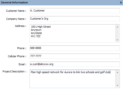
General Information
Project Properties
Set the prediction model that is used to calculate the link availability (see Availability), the default SM Antenna Height and tick “Use Clutter” to include clutter data with the path profiles, untick to work without clutter information. These parameters are stored with the project.

When changing the default SM Antenna Height select Yes to apply the new height to all existing Subscriber Modules, or select No to only apply to new Subscriber Modules.
When changing between working with or without clutter this changes the way that obstructions are portrayed and the version of ITU-R P.526 that is used to calculate obstruction loss. Changing an existing project to use clutter will change the obstruction loss predicted on paths within the project.
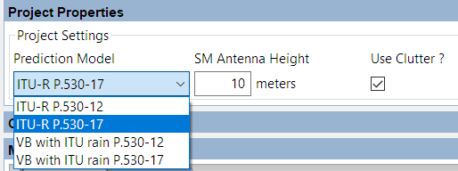
Project Properties
Clutter Heights
Show the heights and colors for each clutter class.
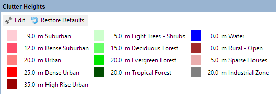
Clutter Heights and Colors
To change the default values select Edit and enter a new height or select the color to access a color chart and select the new color. Select Restore Defaults to return both heights and colors to those defined in LINKPlanner.
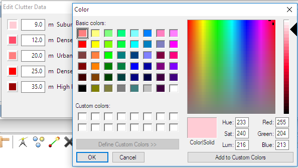
Editing Clutter Heights and Colors
Map
There are potentially two types of map available, depending on the operating system and Internet access.
- Offline Map - available on all platforms
- Online Map - available on Windows providing that there is Internet access
The maps can be enabled/disabled through the View menu.
To easily find a site or link on the map, right-click on the item in the project navigation tree and select Show in Map from the pop-up menu.
Select the objects to show on the map from the Display... option on the Map toolbar, all objects are displayed by default, untick objects not required.
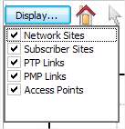
Map Display options
By default, link lines are colored to indicate whether or not their predicted performance meets requirements: red means performance is not acceptable, green means performance is acceptable. It is possible to alter the default colors in the Graphics Page along with the default line style. Additional formatting settings can be applied using Formatting Rules.
Line styles do not change in the online map view.
To select an individual AP when there are multiple overlapping sectors, use the up and down arrow keys to toggle through the sectors.
To change the size or orientation of an AP, select the AP and then click the centre circle and drag to either change the range or orientation, or click one of the outside circles to change the beamwidth.
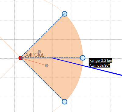
Map AP adjustments
Common Map Icons
The following icons are available in both map views.
Icons appearance may depend on the operating system. Windows icons are shown.
| Icon | Description |
|---|---|
| Reset the zoom/pan for the map to fit the entire project | |
| Select a link or site | |
| Create a new network site. On the online map view you must select the approximate location for the site before the new site dialog (New Network Site Page) is displayed | |
| Create a new subscriber site. On the online map view you must select the approximate location for the site before the new site dialog (New Network Site Page) is displayed | |
| Create a new PTP link | |
| Delete the selected link or site | |
| Display all of the sites, even those which do not have any links associated with them | |
| Display the network site labels | |
| Display the subscriber site labels (not in online map) | |
| Display the path profile preview for existing links and possible links to nearby sites (not in offline map) |
Map Pop-Up Menu
The pop-up menu (Map Pop-up Menu) can be used to access many functions, depending on the item selected, that are also available through the project and equipment pages, but may be faster or easier to apply when viewing the map and surrounding sites. To display the menu, right-click on an item in either the Offline Map (Windows and Mac) or Online Map (Windows only). When running on a Mac, right-click may not be enabled, in which case hold down the control key whilst left-clicking on the item to display the menu.
- Copy: Copy the selected item
- Paste: Paste an item that has been copied
- Duplicate: Duplicate a PTP link
- Edit: Edit the item in a tear-off panel
- Hide: Hide the item from the map view
- Delete: Delete the item from the project
- Change Sites: Change the link to connect two different sites
- Properties: Access the properties dialog, Site Properties Dialog
- Create link from here: Create a PTP link from the selected network site
- Create multiple links from here: Create multiple PTP links from the selected network site
- Create ring: Create a ring of links between consecutive network sites
- Create hub: Create a hub from a network site, only one hub can be created per network site
- Create Access Point: Create an Access Point on a hub (only available if the selected item is a hub site), multiple Access Points can be created on the same hub.
- Attach subscribers: Attach subscribers to the selected Access Point (only available from an Access Point coverage area).
- Set Channel: Choose from the list of channel options to change the frequency assigned to the Access Point (only available from an Access Point coverage area).
- Change Access Point: Change which Access Point an SM is connected to (only available from an SM link to an AP). This option provides a list of other Access Points which are within the maximum range and sector coverage of the SM. The SM configuration is preserved if valid on the new Access Point, otherwise default values are used.
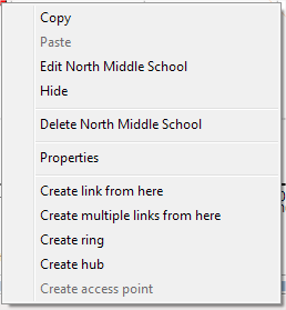
Map Pop-up Menu
Editing items
The Edit command opens the tear-off window with the appropriate panel for the item. This window will float above the main LINKPlanner window until it is closed, allowing quick and easy viewing of the changes directly on the map.
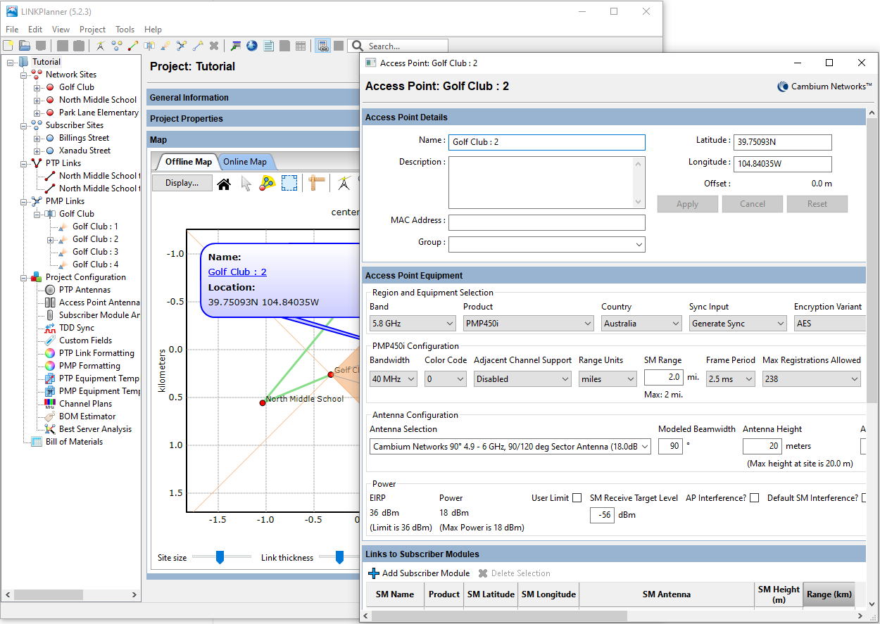
Edit Window Floating over Map
Creating Access Points
The first Access Point is added when the hub site is created and will use the default settings with an Antenna Azimuth of 0 degrees (North), subsequent Access Points will use the settings of the first Access Point. Configure the first Access Point, using the Edit option, see Access Points, before adding additional access points to the hub site. Additional Access Points will have their default Antenna Azimuth offset from the previous one by the beamwidth of the antenna or the Modeled Beamwidth if it has been set to a different value.
Attaching Subscribers
The Attach subscribers command opens the Add a new SM dialog window, New Subscriber Module Page. This window displays the subscriber sites that are within range of the access point. Any subscriber sites that are not linked to an access point will be selected by default. Clicking OK in this dialog will create PMP links between the access point and the subscriber sites.
Offline Map
The Offline Map is a schematic plan of the sites and links that have been entered in this project. There are many functions that are supported through the Offline Map, see Offline Map for further details.
Online Map
The embedded Online Map view is available when LINKPlanner is running on Windows. The map can be used to view and edit the project. See Common Map Icons for more information.
To show the locations of sites operated by Crown Castle, tick the Crown Castle sites in the Layers menu on the top left hand corner of the map. When on a low map resolution this shows the number of sites in an area. To see the individual sites zoom in to a higher resolution for the area required.
To create a Network Site at the location of a Crown Castle Site, select the Crown Castle icon ![]() , which will pop-up a menu showing information about the site and then select Create network site here.
, which will pop-up a menu showing information about the site and then select Create network site here.
There are some keyboard shortcuts available in the online map:
- n - activates the New Network Site function
- s - activates the New Subscriber Place function
- l - activates the New PTP link function
- f - activates the Fit Map function
Press escape to cancel any of these functions
To reposition a site in online map, simply select the site and drag it to the new location, then select OK in the Reposition place pop-up menu. To return to the original location select Cancel. If the site has connected PTP or PMP links all the associated links will move with the site and the new path profiles requested automatically.
To reposition an individual AP from its central hub location, zoom into the area of the hub and select the AP, the site icon will turn white, select the site icon and drag to the new position. The AP will move to the new position and path profiles for all connected subscriber modules will be requested automatically. A dotted line is shown on the map to connect the AP back to its associated hub site. The maximum distance an AP can be moved with respect to the hub site is 100m.
Large projects may experience poor performance due to the time that it takes to refresh the map. If the project is large, you may wish to disable the online map view in the Views menu.
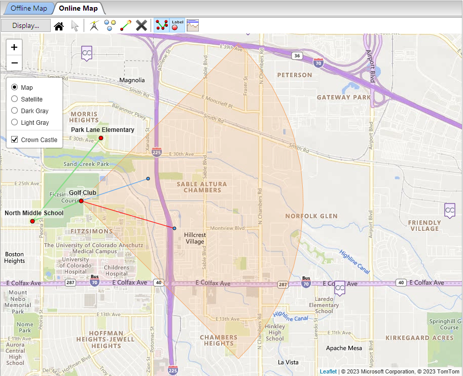
Online Map
Google Earth
To export the link or project to Google Earth, on Windows or Mac, select either the link or the project node in the navigation tree and then select the Google Earth icon ![]() from the main toolbar.
from the main toolbar.
Google Earth must already be installed and requires Internet access.