Access Points
The Access Point connects to one or more Subscriber Sites to create links to Subscriber Modules. In a cnRanger network the Access Point represents the RRH and the BBU common radio parameters.
Creating Access Points
To create a new Access Point, either click Project, New Access Point, click New Access Point  or add from the Access Points view on the Hub Page, see Access Point View on Hub Page. If creating through the New Access Point options, the New Access Point page is displayed.
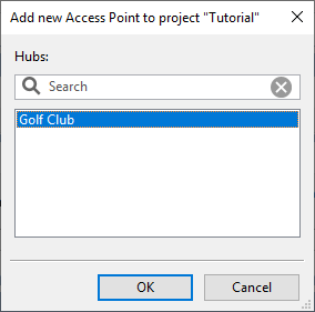
The list of available Hub sites is displayed. The search field narrows the choice when there is a large number of Hubs in the list. Select a Hub Site from the list and hit OK.
The Access Point is then listed in the project navigation tree below selected Hub Site.
Deleting an Access Point
To delete an Access Point, select the Access Point in the navigation pane, right click and choose delete from the pop-up menu, or select Project, Delete Access Point name, in the same manner as deleting Hub Sites, see Delete Hub Site.

- Deleting an Access Point will delete all links to Subscriber Modules connected to the Access Point. The Subscriber Sites will not be deleted and will be available to connect to other Access Points.
Splitting an Access Point
To split an Access Point, select the Access Point in the navigation pane, right click and choose Split access point and then choose from 2, 3 or 4 access points on the pop-up menu, or select the Access Point in the map and follow the same process in the right click pop-up menu. The Split Access Point function will create additional duplicate Access Points with identical configuration to the original. The subscribers from the original are distributed between the original and new access points alternately, based on SM bearing from AP boresight, such that each AP has a similar azimuth distribution of subscribers.
Access Point Page
The Access Point page includes the following features:
- Each section begins with a blue title bar. Click on this bar to open or close the section.
- The numeric data entry fields can be incremented or decremented in steps by using the up and down arrow keys. Use this feature to evaluate the impact of step changes on link performance.
- If a field is highlighted in pink, its value is out of the permitted range.
Access Point Details
Enter the Name and Description of the Access Points. The MAC Address of the equipment may also be added. The MAC Address must be included for the PMP 450 configuration file to be created. Select a Group from the drop down list or type in a new Group name into the empty field. When an Access Point has Subscribers connected the contact information for the Sales Contact for the location of the Access Point will be shown. To update this information click Refresh
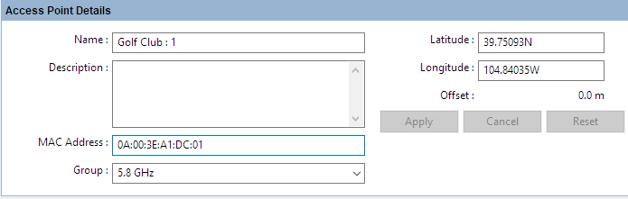
Access Point Details
To move an Access Point to a different location from the hub site coordinates enter new coordinates in the Latitude and Longitude fields. The Offset value will show the distance between the Access Point and the central hub location, the AP can only be moved up to 100 m (328 ft) from the central hub location. If the distance is greater than this, the offset value is shown in red and it is not possible to select Apply. When the offset is less than 100m select Apply to move the Access Point to the new location, which will automatically request new profiles for all subscribers connected to it. Select Cancel to return to the previous value or select Reset to move the AP back to the central hub coordinates.
Access Point Equipment
Select the equipment, regulation and parameters for the Access Point. The fields that are displayed in the “Access Point Equipment” box will change depending on the type of equipment selected. For example, when a PMP 450i is selected, the Color Code field is displayed.
Some parameters are required when configuring the product but are currently not used in the LINKPlanner calculations, they will be used in future releases. These items are identified as “(information only)” in the descriptions below.
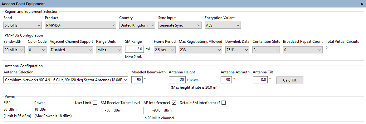
Access Point Equipment
Region and Equipment Selection
Band: Select the frequency band used by the Access Point.
Product: Select the PMP product.
Color (PTP 700 HCMP only): Select the color of the radios, the same color will be used at the Access Point and for all connected subscribers.
Country: Select the country in which the Access Point is located.
Sync Input (PMP 450 and 450i only): Select the synchronization option for the link (information only).
Encryption Variant (PMP 450 and 450i only): Select the encryption option for the link, used for product selection only.
MIMO Mode (PMP 450m and ePMP 3000 only): Select the MIMO operating mode. For PMP 450m choose Sector mode to report AP performance in Legacy mode using the standard PMP 450 capacity scheduler or choose Mu-MIMO to report cnMedusa AP Performance. For ePMP 3000 choose Off to report AP performance in Legacy mode with no beamforming gain or multiple simultaneous users or 4x2 Single User to include 3 dB downlink beamforming gain without multiple simultaneous users.
RRH Number (cnRanger only): Select the RRH number, this number must be unique on a BBU Group.
LTE Band (cnRanger only): Read only value showing the LTE Band number for the Frequency Band selected.
I/O Connectivity (N500 Only): Select Expanded to get the additional IO port, used for product selection only.
Sync Input (N500 Only): Select the synchronization option for the link.
Configuration
Band Setting (N500 Only): Select ISM or Licensed.
T/R Spacing (N500 Licensed Only): Select the difference between transmit and receive frequencies (MHz).
Bandwidth: Select the channel bandwidth.
Channel (60 GHz cnWave Only): Select the Frequency and Channel number.
Modulation Type (N500 ISM Only): Select the group of modulation modes to use.
Color Code / Golay Code: Select the Color Code for the Access Point (information only), called Golay Code on 60 GHz cnWave.
Adjacent Channel Support (PMP 450 family Only): Select Enabled if using adjacent channels on adjacent sectors. This option only applies to the 3 GHz bands (all SMs) and to the 5GHz band for PMP 450b SMs.
Polarity (60 GHz cnWave Only): Set to Odd or Even. If the two sectors on the DN are set to opposite polarities this represents a Hybrid mode and the throughput is halved.
Range Units: Select the units for the SM Range.
SM Range: Set the maximum range for the Access Points sector size. Subscriber sites beyond this range will not be shown as valid subscriber module options and if the SM Range is reduced after adding Subscribers, any subscribers beyond this range will be shown as invalid (i.e. in red).
SM Modulation Mode (N500 Only): Select the modulation mode to be used by the SM equipment.
SM Maximum Mod Mode (N500 Only): Select the maximum modulation mode that the SM equipment will use in adaptive mode. Only displayed when Adaptive modulation is selected.
SM Minimum Mod Mode (N500 Only): Select the minimum modulation mode that the SM equipment will use in adaptive mode. Only displayed when Adaptive modulation is selected.
AP Modulation Mode (N500 Only): Select the modulation mode to be used by the AP equipment.
Hop Pattern (N500 only): Select the uniform step interval for DTS modulations. A value of 0 sets the frequency to a single channel, a value of 1 creates a pseudo random hopping sequence. A value of 1 must be used when Modulation Type = FHSS.
MMS Hop Offset (N500 only): Select the MMS Hop Offset for the link.
AP Max Payload Bytes (N500 only): Set the maximum packet size at the AP. Maximum value is 1600 Bytes. Minimum value for fixed modulation mode is 64 Bytes, in adaptive mode, the minimum may be higher than this dependent on the configured Max and Min Modulation modes. Reducing the packet size will reduce the data rate from the quoted data rate per mode.
SM Max Payload Bytes (N500 only): Set the maximum packet size at the SM. Maximum value is 1600 Bytes. Minimum value for fixed modulation mode is 64 Bytes, in adaptive mode, the minimum may be higher than this dependent on the configured Max and Min Modulation modes. Reducing the packet size will reduce the data rate from the quoted data rate per mode.
Frame Period: Select the Frame Period.
Downlink Data (cnRanger, PMP 450 and 450i Only): Set the proportion of the link to be used for downlink data.
SSF (cnRanger only): Set the Special Subframe Configuration
Maximum Mod Mode (ePMP and 60 GHz cnWave Only): Set the maximum modulation for the Access Point on the downlink to all Subscribers.
DL/UL Ratio (ePMP Only): Select the required DL/UL Ratio.
Contention Slots (PMP 450 and 450i Only): Set the number of contention slots required.
Broadcast Repeat Count (PMP 450 and 450i Only): Select the value required (information only).
Total Virtual Circuits (PMP 450 and 450i Only): Calculated value based on the number of Subscriber Modules, 1 per Subscriber Module plus 1 additional circuit for each Subscriber Module which has High Priority Channel set to Enabled.
CN Capacity Limit (60 GHz cnWave Only): percentage of maximum traffic which is allowed for use by Client Nodes, with the remainder reserved for use by the mesh links to other DNs.
Max Registrations Allowed (cnRanger, ePMP, PMP 450 and 450i Only): Set the maximum number of Subscribers allowed on the Access Point.
Max CN Registrations Allowed (60 GHz cnWave Only): Set the maximum number of Client Nodes allowed on the DN, noting that each DN can also support mesh links to two other DNs, not shown in LINKPlanner
Max Slaves Allowed (PTP 670 and 700 HCMP Only): Set the maximum number of Slaves allowed on the Access Point. Note that in the list views this will be shown under the column heading Max Registrations Allowed.
Synchronization Source (ePMP Only): Set the required Synchronization Source, select None to use the Integrated or Unsynchronized Connectorized Access Point.
Sync (PTP 670 and 700 HCMP Only): Select the synchronization setting for the link, either Disabled or PTP-SYNC.
TDD Frame Mode (PTP 670 and 700 HCMP Only): Select the TDD Frame Mode, either Standard or Expert for Asymmetry Expert Mode.
Symmetry (PTP 670 and 700 HCMP Only): Select the link operation (Adaptive, Symmetric, 2:1, 3:1 or 4:1 - options are dependent on bandwidth and other configuration settings).
DL Timeslots (PTP 670 and 700 HCMP Only): In Expert mode set the number of DL Timeslots to be shared between the slaves.
UL Timeslots (PTP 670 and 700 HCMP Only): In Expert mode set the number of UL Timeslots to be shared between the slaves.
Dual Payload (PTP 670 and 700 HCMP Only): Allow dual-payload modulation modes for better throughput.
Highest Mod Mode (PTP 670 and 700 HCMP Only): Select the highest modulation mode for the Ethernet traffic to limit the maximum throughput rate, default is 256 QAM 0.81 (no limit). Dual or Single will be automatically selected depending on the setting for Dual Payload.
Lowest Ethernet Mode (PTP 670 and 700 HCMP only): Select the lowest modulation mode for the Ethernet traffic to achieve the required throughput rate, default is BPSK 0.63 Single.
Frequency Configuration (N500 only)
Band Start: Select the lower band edge frequency, default for 900 MHz ISM is 902 MHz.
Band Stop: Select the higher band edge frequency, default for 900 MHz ISM is 928 MHz.
Exclude Lower: Select the lower frequency to be excluded, a value of 0 MHz indicates no lower limit. This value must be between the Band Start and Band Stop frequencies.
Exclude Upper: Select the upper frequency to be excluded, a value of 0 MHz indicates no upper limit. This value must be between the Exclude Lower and Band Stop frequencies.
Antenna Configuration
Antenna Selection: Select the antenna for the Access Point.
Modeled Beamwidth: Set the beamwidth angle that will be used for planning purposes. This will control the appearance of the access point on the map views and it will be used to determine if subscriber sites are in range.
Antenna Height: Select the height of the Access Point above ground level.
Antenna Azimuth: Set the bearing of peak of beam of Access Point antenna.
Antenna Tilt: Set the angle of mechanical tilt of the access point antenna, enter downtilt as a negative value (not available for omni antennas).
Calc Tilt: Select to calculate the optimum mechanical tilt angle for maximum throughput.
Calculate Loss: (N500 Only). Tick the Calculate box to select the type of cable that connects the radio to the antenna. The Cable Loss field is automatically updated.
Cable Length: (N500 Only). The length of cable required to connect the radio to the antenna. The Cable Loss field is automatically updated.
Cable Loss: Loss of the cable between the Access Point and the antenna, read only value for most antenna options.
Power
EIRP: Read only value for all products except PMP 450m, showing the EIRP of the antenna, if the country selected has a regulatory limit this value is shown in brackets underneath.
Power: Read Only. If the country selected has a regulatory limit (or an implied limit to meet the EIRP limit) the value is shown as “Max Power” in brackets underneath. To set the transmit power for the Access Point tick the User Limit box and enter the value in the box below it.
SM Receive Target Level: (ePMP and 450 family only) Set the receive power required at the Access Point from each of the Subscribers.
ATPC HCMP Master Target Rx Power (PTP 670 and 700 HCMP Only): Set the receive power required at the Access Point from each of the Slaves. Note that in the list views this will be shown under the column heading SM Receive Target Level.
AP Interference: This is the amount of site noise in the selected channel bandwidth, expected at the antenna connector of the AP. This noise is assumed to be a constant power added to the thermal noise of the front end of the radio. The bandwidth displayed depends on the bandwidth selected in the Equipment Settings box (in this example it is 20 MHz). To enter Interference, tick the box and update the default value. If the Access Point has been set up and background power measurements are available, then use these measurements.
Default SM Interference: Select this option to set the same interference level to every SM attached to the AP. This is the amount of site noise in the selected channel bandwidth, expected at the antenna connector of the SM. This noise is assumed to be a constant power added to the thermal noise of the front end of the radio. The bandwidth displayed depends on the bandwidth selected in the Equipment Settings box (in this example it is 20 MHz). To enter Interference, tick the box and update the default value. Use the Interference on the Subscriber Module Equipment to adjust the level for an individual SM.
Channel Selection
This section is only displayed if a Channel Plan exists for the given Band, Product, Country and Bandwidth.
Channel Plan: Select the Channel Plan required.
Channel: Select the Frequency required for the Access Point.
To update subscriber module parameters and performance calculations after editing Access Point parameters, select Calculate Now, unless Automatic Calculations are enabled, see Project Toolbar .
Calculating Tilt Angle
To calculate the optimum tilt angle for an Access Point (the mechanical tilt required to give maximum throughput) select the Calc Tilt  option to display the Calculate Tilt Dialog.
Attach all the required subscriber modules to the Access Point before running this command.
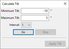
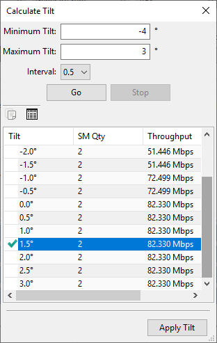
Calculate Tilt Dialog
The dialog shows a number of options:
Minimum Tilt: Set the minimum tilt angle to consider when running the calculations. The default is the minimum downtilt of the antenna.
Maximum Tilt: Set the maximum tilt angle to consider when running the calculations. The default is the maximum uptilt of the antenna.
Interval: Set the step interval to define the intermediate tilt angles in the results list. Use a large value if the difference between the Minimum and Maximum is large, reduce the interval for smaller ranges.
Go: Start the calculation.
Stop: Stop the calculation from running.
Apply Tilt: Apply the selected tilt angle to the access point. The access point will not update unless this command is executed.
When the calculation has finished running, the results are shown below the configuration settings (Completed Tilt Calculation Run). The angle that offers the maximum throughput is shown with the tick and is automatically selected. If multiple angles offer the same throughput then the middle angle is selected. To use a different angle, highlight the required row. Select Apply Tilt to update the Access Point to the new tilt angle. The toolbar provides commands to copy the results to the clipboard or export the results to a CSV file.
Completed Tilt Calculation Run
Subscriber Module Slot Allocation
This pane is only displayed for PTP 670 and PTP 700 HCMP when the TDD Frame Mode is set to Expert. In the left hand side of the pane set the number of slots for DL and UL for each subscriber in the DL Slot Request and UL Slot Request columns. The maximum number of slots per subscriber in each direction is 15. The total number of slots in a direction for all subscribers must not exceed the number of timeslots allocated in that direction in the Access Point Equipment.
Set the maximum limit of slots that can be used for each subscriber in the DL Slots Limit and UL Slots Limit. This parameter is not used by the LINKPlanner calculation, but is displayed in the installation report for use during commissioning.
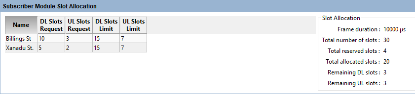
SM Slot Allocation for 4 Max Slaves Allowed
The right hand side of the pane provides a summary of the slot allocations:
Frame duration - calculated value based on the bandwidth and SM Range, used for synchronization
Total number of slots - sum of the DL Timeslots and UL Timeslots entered in the Access Point Equipment.
Total reserved slots - one slot is reserved in both DL and UL for any subscribers in Max Slaves Allowed, which have not been connected.
Total allocated slots - sum of DL Slots Request and UL Slots Request
Remaining DL slots - number of DL slots that are available to allocate to subscribers, equal to:
DL Timeslots - total DL Slots Request - (Total reserved slots / 2)Remaining UL slots - number of UL slots that are available to allocate to subscribers, equal to:
UL Timeslots - total UL Slots Request - (Total reserved slots / 2)
Mesh Links
Mesh Links are only available for 60 GHz cnWave products. View, add, delete and modify Mesh Links on the Distribution Node (DN). To manage the information displayed in the list, see Managing List Views.
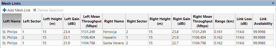
Mesh Links View on Access Point page
Links to Subscriber Modules
View, add, delete and modify Subscriber Modules on the Access Point. To manage the information displayed in the list, see Managing List Views.
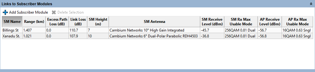
Links to Subscriber Module View on Access Point page
To add additional Subscriber Modules at the Access Point, click  . A list of available subscriber sites will be displayed. Any subscriber sites which are not connected to the Access Point will be highlighted. To create an additional Subscriber Module at the same subscriber site select the required subscriber site and a duplicate Subscriber Module is created.
To delete a Subscriber Module at the Access Point, select the Subscriber row and click  .
.
If the access point is configured with the PMP 450m product and the Operating Mode is set to Downlink Mu-MIMO then the Links to Subscriber Modules toolbar includes the Highlight ungrouped command. To identify subscribers which are not grouping, select this option and the Links to Subscriber Modules list displays the MU-MIMO Grouping OK? column, sorts the table on this column and highlights any subscriber modules that are not grouped.
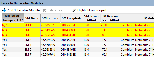
Highlighting ungrouped subscriber modules
Performance Summary
This section provides a summary of the Maximum Usable Modulation Modes of all the PMP Links on the Access Point and the Mean Predicted Throughput per modulation mode and for the AP. These values assume that all subscribers are evenly loaded and using the modulation modes shown, it does not include the capacity limits of individual subscribers.
The performance summary can be saved as a CSV or Excel file by clicking View in Spreadsheet ![]() .
.
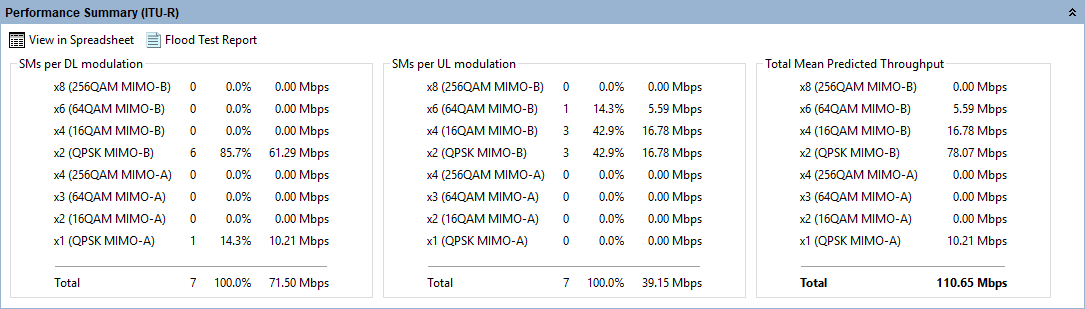
Performance Summary for the Access Point
A PMP Link will only be included in the summary if it supports a modulation mode at the required performance level in both directions of the link. A warning will show the number of PMP Links which don’t meet this criteria.
Bill of Materials for Access Point
LINKPlanner automatically calculates the Bill of Materials (BOM) for the required components of the Access Point. The Access Point BOM contains the list of part numbers and associated quantities. To add additional items to the BOM, click New Extra  . A list of optional extras for the Access Point will be displayed. To add items to the BOM tick the box next to each item required and click OK. The item will appear in the main list, where the quantity can be adjusted by selecting the number in the Qty column and adjusting as required. To delete optional items from the BOM list, highlight the items and click Delete Extra
  . A star denotes optional extras which have been added to the automatic BOM items. To power the AP from the switch tick the Power from switch? box.
When Power from switch is selected, where possible the PoE and line cord are removed from the BOM, which may result in the kit part number changing to a different kit that doesn’t include a PoE. This is not available for all products and country variants.
The Power from Switch option is only available if the network/hub site has a switch attached to it, see Adding Switches and the product selected can be powered by the switch, which includes most of the PoE powered Cambium radios.
If TX2000 is the Sync option on PTP 670 HCMP the AP will automatically be configured to be powered from the switch.
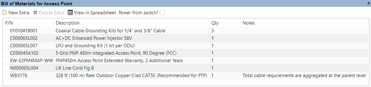
Bill of Materials for Access Point
P/N: The Cambium part number. If the component is not supplied by Cambium, this is set to ‘(no part number)’.
Description: Description of the components.
Qty: Quantity required.
Notes: By default this displays information about certain items, such as whether they are obsolete, or to prompt for additional required information. This field can be edited to allow additional information to be added to the item. The default text is returned if the edited text is deleted. When information is displayed in the Notes field, items will only be aggregated at the higher level BOMs if the Notes field contains identical information as well as being the same part number.
Bill of Materials for Subscriber Modules
The Subscriber Modules BOM displayed in the Access Point page contains an aggregate view of all the equipment required for the Subscribers connected to the Access Point. This BOM cannot be edited at this level. To change the quantities or add Optional Extras, select the individual Subscriber Modules.
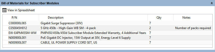
Aggregate Bill of Materials for Subscriber Modules on an Access Point
Viewing & saving the BOM file in MS Excel
To view the Access Point BOM or Subscriber Module Aggregate BOM in Excel, click View in Spreadsheet ![]() in the appropriate BOM section. Once in the spreadsheet the file can be saved as normal.
in the appropriate BOM section. Once in the spreadsheet the file can be saved as normal.
All numeric only part numbers consist of 11 digits, if the number displayed is only 10 digits the part number should start with a zero.