Setting Hot Standby Protection (1+1)
Hot Standby is available on PTP 700, PTP 800, PTP 810 and PTP 820 links and involves configuring two units at each end of the link to operate as primary and secondary (standby) units. For a more detailed understanding of 1+1 Hot Standby, see the appropriate product User Guide.
Hot Standby can be enabled as described in Link Description and Equipment. Once enabled, the Project Navigation Tree shows the link node and then up to four paths as sub-headings to the main link, as shown in Navigation Tree for Protected (1+1) link.
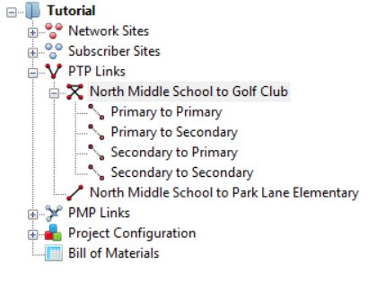
The link node gives access only to the Link Description, Equipment Selection and Bill of Materials aspects of the link configuration, see Link Node Information for Protected (1+1) link. To access all other sections of the Link Page select one of the four paths, e.g. Primary to Primary.
Hot Standby Configuration at Each End
Select the required path for the protected link. In addition to the normal parameters as described in Link Description and Equipment, links operating Hot Standby have the following additional attribute displayed:
Antenna Configuration: There are up to 4 options which can be selected to match the possible configurations for Hot Standby when using an ODU Product or PTP 820.
- Common Antenna - Symmetric Coupling
- Common Antenna - Asymmetric Coupling - default setting
- Redundant Antennas - PTP 700 and PTP 800 Only
- Spatial Diversity, see Setting Diversity
There are 5 options which can be selected to match the possible configurations for Hot Standby when using an IRFU product.
- Equal Splitter - default setting
- Equal Splitter MHSB Ready
- Unequal Splitter
- Unequal Splitter MHSB Ready
- Spatial Diversity, see Setting Diversity
There are 3 options which can be selected to match the possible configurations for Hot Standby when using a PTP 820i product.
- Common Antenna - Asymmetric Coupling - default setting
- Spatial Diversity (Split End), see Setting Diversity
- Spatial Diversity (Standard), see Setting Diversity
The primary and secondary parameters at each end can be configured as described in Configuration at Each End, by selecting the following paths:
- Primary to Primary
- Primary to Secondary
- Secondary to Primary
- Secondary to Secondary
Although the parameters can be configured through either the primary or secondary interface, some parameters are common to both configurations at the same end of the link. Any changes made to either primary or secondary configuration will automatically be reflected in the other configuration at that end of the link.
Antenna Type: If one of the common antenna protection options has been selected this value will be the same for both primary and secondary. If the redundant antennas or spatial diversity option have been selected then a different antenna can be chosen for primary and secondary. If using an FCC regulation Cat B, Cat B1 or Cat B2 antennas can be used as a receive only diverse antenna in locations where a Cat A primary antenna is required. In such locations these antennas must not be used for transmit, see PTP 800 Series User Guide or PTP 810 Series User Guide for further details on the correct way to commission the PTP 800 and PTP 810 modems for use with these antennas.
Antenna Height: If one of the common antenna protection options has been selected this value will be the same for both primary and secondary. If the redundant antennas or spatial diversity option have been selected then a different antenna height can be chosen for primary and secondary.
Diversity Spacing: This field is only shown when the Antenna Configuration is set to Spatial Diversity and it shows the difference in height between the Primary and Secondary antennas. Improvement in availability will only occur when this value is greater than zero, see Setting Diversity.
Feeder Loss: This field will incorporate the coupler loss in addition to any waveguide loss. Any User Defined additional loss which has been included will be the same for both primary and secondary remote antennas for any of the common antenna protection options, but can be different for primary and secondary if the redundant antennas or spatial diversity option have been selected. The symmetric coupler will have the same loss for both primary and secondary, whereas the asymmetric coupler has a lower loss for the primary and higher loss for the secondary. For the IRFU the losses will always be defined by the more complex Losses spreadsheet as described in Long Waveguide, as the losses are not the same for both transmit and receive.
Maximum EIRP: The EIRP will often be different for the primary and secondary, in the majority of cases the primary will have the higher value. If the secondary has a higher value than the primary, a warning will be shown on the display, as this might violate the terms of the license.
The IRFU and RFU-A in Standard configuration only transmit through the Primary Antenna and Feeder System, therefore for Spatial Diversity using an IRFU or RFU-A (Standard), the EIRP is calculated using the Primary Antenna Gain and Feeder Losses. The Secondary Maximum EIRP and Maximum Power will be the same as for the Primary and there are no separate User Limits for the Secondary. The receive path uses the Secondary Antenna Gain and Feeder Losses.
Maximum Power: This field can be set independently for primary and secondary, unless using IRFU or RFU-A (Standard) Spatial Diversity or PTP 810.
PTP 810 only supports a single transmit power setting during installation. It also supports a setting for coupler loss, which when using a common antenna is the difference in coupler loss between the primary and secondary path. For Spatial Diversity the coupler loss is any additional loss due to lower antenna gain and feeder loss on the secondary path. The coupler loss is shown on the Installation Report. The Secondary Maximum EIRP and Maximum Power are calculated from the Primary Maximum Power and there are no separate User Limits for the Secondary.
Tx Frequency: This value will always be the same for primary and secondary.
Tx Capacity Limit: PTP 800 Only. This field can be set independently for primary and secondary.
Link MMU Model: PTP 810 Only. This value will always be the same for primary and secondary.
Interference: This value will always be the same for primary and secondary.
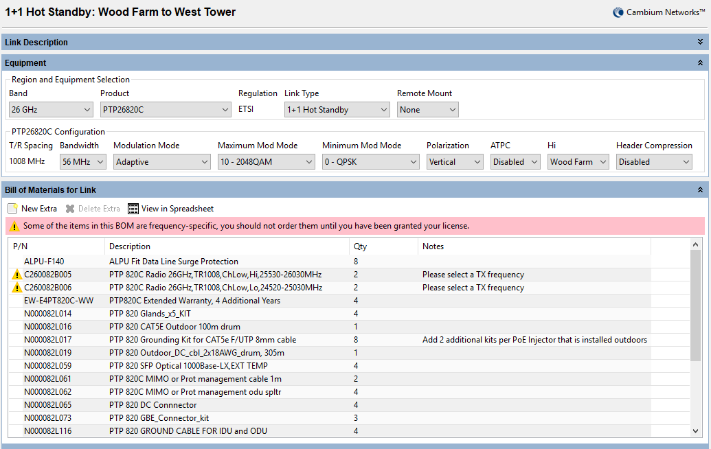
Hot Standby Bill of Materials
The Bill of Materials is displayed at the link node level and shows the full set of equipment required for both the primary and secondary units. For PTP 800, Hot Standby can be operated with either in-band or out-of-band management. If out-of-band management is required then additional items may be required to make up a full set of equipment, which can be selected via the New Extras  icon, see Bill of Materials Optional Extras.
Hot Standby Performance Summary
The performance summary information is shown separately for each path and can be accessed by selecting the appropriate path, for example Primary to Secondary, from the navigation tree. The required performance parameters can be set independently for each path and are defined in the usual way, see Performance Summary.
If the predicted performance of the primary to primary path is below requirements, then the main link node will be displayed in red. If the performance of any of the other paths is below requirements then the associated sub-path in the navigation tree will be shown in red, but will not affect the annotation of the link node, the map display or the link table . If a particular path is not considered relevant to the performance of the link, it can be “switched off” by setting the following:
- Mean IP Required to 0.1 Mbps
- Min IP Availability Required to 0.0000%

For PTP 800 and PTP 810 Spatial Diversity improvement is only applied to the lowest configured modulation mode, therefore it will always be included in the Link Summary parameter Lowest Mode Availability. It will usually also be included in the Min IP Availability Predicted, however if the Min IP Required is greater than that supported by the Minimum Mod Mode, there will be no spatial diversity improvement included in the Min IP Availability Predicted. If IRFU or RFU-A (Standard) are selected with Spatial Diversity the Secondary to Secondary performance is not relevant as the transmit path is always through the primary antenna.
Hot Standby Reports
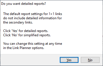
There are two levels of report available in Hot Standby. By default a standard report is produced, which concentrates on the performance of the primary to primary link or a detailed report can be produced which details all four paths. When the protected link option is selected for the first time by a user the following message is displayed allowing the user to choose the type of report.
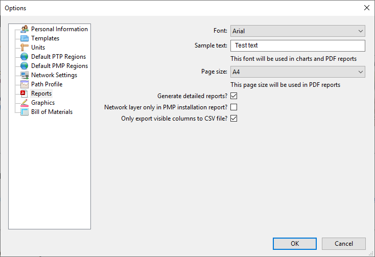
The type of reports can be changed at any time by clicking Tools, Options, Reports and then selecting or deselecting the Generate detailed reports option.
The proposal and installation reports are created for a given link, not path, in the usual way, see Creating Reports. The level of detail presented will depend upon the detailed reports selection and which product is selected. The standard reports only show performance information for the primary to primary path. If a common antenna has been selected, or the link is PTP 810, only one set of installation notes will be produced for each end of the link, any parameters which might be different between the primary and secondary units will be clearly specified. This includes the predicted receive power at both the primary and secondary units at one end from the primary unit at the other end. If redundant antennas or spatial diversity have been selected separate installation notes will be produced for the primary and secondary units for PTP 800, as several parameters are likely to be different. PTP 810 will still show a single section for each end, but include all parameters which might be different.
The detailed reports contain both installation and performance information for each of the path combinations, with the significant changes outlined in the following sections.
Detailed Proposal Report
The throughput information for each end of the link and the link summary information is shown for each of the paths.
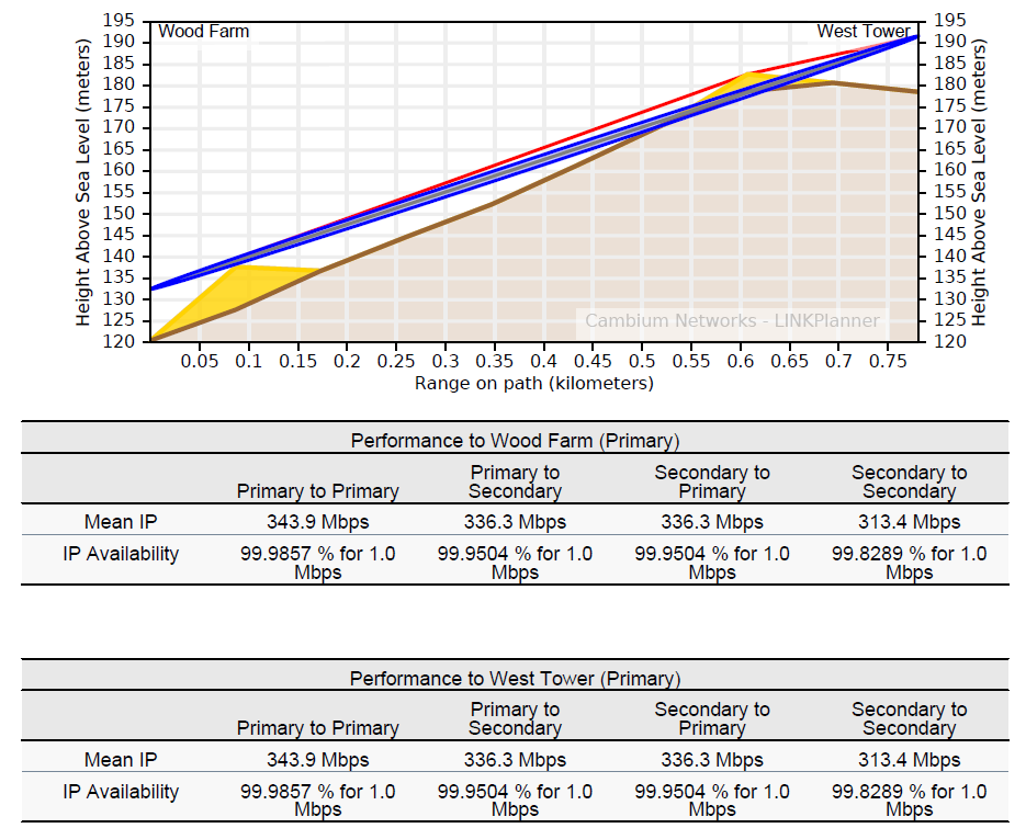
For both sets of performance information the primary to primary notation refers to the left end to right end of the link, in this example Wood Farm to West Tower.
For the Performance to West Tower the information is shown for the performance received at West Tower when:
- Primary to Primary - both Wood Farm and West Tower are set to primary.
- Primary to Secondary - Wood Farm is set to primary and West Tower is receiving a signal on its secondary unit.
- Secondary to Primary - Wood Farm is transmitting on its secondary unit, whilst West Tower is still receiving on its primary unit.
- Secondary to Secondary - both Wood Farm and West Tower are using their secondary units
Detailed Installation Report
The initial sections of the report (link summary, path profile and link configuration) are shown for the primary to primary path. For PTP 800 the site installation notes are given for both the primary and secondary units at each end of the link, however for PTP 810 it is given as a single report for each end, showing any difference in primary and secondary parameters as required. The BNC Target Voltage and Predicted Receive Power are given for both the primary and secondary units with the other end of the link operating on primary.
If the values are required to verify the secondary to secondary path, then the Predicted Receive Power can be estimated quite closely for the common antenna configuration. The BNC Target Voltage can be derived from the received signal level using the RSSI voltage table given in PTP 800 Series User Guide or PTP 810 Series User Guide. Assuming that the same power level is used for both primary and secondary then the impact will be as follows:
- Symmetric Couplers - no change in predicted receiver power
- Asymmetric Couplers - the predicted receive power will drop by 5.4 dB compared with the secondary receive power level.
If the transmit powers are different for primary and secondary then the offset will have to be adjusted according to the difference. Equally if different antennas are used for primary and secondary the predicted receive power for the secondary to secondary path will be changed (with respect to the primary to primary path) by the sum of the difference in antenna gains at each end of the link.
For both PTP 800 and PTP 810 the performance information is given for all four paths, in a similar manner to the detailed proposal report.