Configuration at Each End
Use this section to evaluate different antenna configurations at each end of the link. Enter data about the antenna, transmission power and interference density (at both ends). In response, the Performance Summary section is updated automatically to show the effect upon the Mean Throughput, Minimum Throughput and Availability. The two ends are each divided into three parts:
- Data that affects both transmission and reception: Antenna, Diversity Spacing, Antenna Height and Cable Loss.
- Data that affects transmission only: Maximum EIRP, Maximum Power.
- Data that affects reception only: Interference Density.
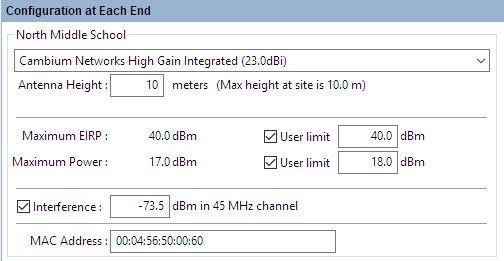
Configuration at Each End (one end shown)
Antenna: Select the required antenna from the drop-down list. The list can be sorted by any column by clicking the column heading. If operating in the unlicensed band and the required antenna is not in the list, click Other... and enter the details in the User Defined Antenna page. Antennas may also be viewed, created, edited and deleted from the Available Antennas page. Licensed band antennas may only be viewed, at present only Cambium supplied antennas are supported at these frequencies.
Antenna Configuration: (PTP 700 1+1 HSB and 2+0 configurations only) Select the required coupler or antenna configuration.
Antenna Height (meters): This is the height of the antenna AGL, not the height above the building on which it is mounted. The Profile visualization is automatically updated in response to changes in Antenna Height.
Positioner: (PTP 450i and PTP 670 Only) Tick this box to add the positioner equipment to the BOM. Select for each end of the link which requires a positioner. This is only available for integrated antennas.
Diversity Spacing (meters): In licensed band displays the diversity spacing as a read only parameter, to change the diversity spacing adjust the height of the secondary or diverse antenna. When in the unlicensed band this field is only displayed if an external antenna is selected and the Spatial Diversity box is ticked, set the diversity spacing height required. Tick the reflection mitigation to use the diversity to combat reflections, leave unticked for protection against tropospheric multipath. See Setting Diversity, for more information on how diversity operates for the different products and configurations.
Coupler Loss: (PTP 700 1+1 HSB and 2+0 only) Read only parameter showing the loss of the coupler when selected
Cable Loss (dB): This field is not displayed for INTEGRATED antennas. If a non-integrated antenna is used, power may be lost in the cable connection between the radio and the antenna, therefore the Cable Loss must be estimated. To enter Cable Loss: either enter the estimated loss in the dB field; or tick the Calculate box, select the type of cable or waveguide that connects the radio to the antenna (the cable choices available depend on the frequency band selected), and enter the length. In response, the dB field is automatically updated.
Scan Loss (dB): (PTP 700 BSA Only) If BSA antennas are not aligned at polar coordinates = (0, 0), Scan Loss must be estimated from the alignment error angles (Azimuth & Elevation Offset angles). To enter Scan Loss: either enter the estimated loss in the dB field; or tick the Calculate box, enter Azimuth and Elevation Offset values in degrees. In response, the dB field is automatically updated.
Maximum EIRP (dBm): The maximum available Equivalent Isotropic Radiated Power. The default value is determined by the Band, License, Product and Antenna. If a lower user-defined limit is required, tick the User Limit box and enter the value. In response, the default Maximum EIRP is automatically reset to the User Limit.
Maximum Power (dBm): The maximum available transmission power. The default value is determined by the Band, License, Product and Antenna. If a lower user-defined limit is required, tick the User Limit box and enter the value. In response, the default Maximum Power is automatically reset to the User Limit.
Max Payload Bytes: (N500 only) Set the maximum packet size. Maximum value is 1600 Bytes. Minimum value for fixed modulation mode is 64 Bytes, in adaptive mode, the minimum may be higher than this dependent on the configured Max and Min Modulation modes. Reducing the packet size will reduce the data rate from the quoted data rate per mode.
Tx Frequency: (PTP 550, PTP 450i CBRS and 60 GHz cnWave Only) To change transmit frequencies for the link, click on Select.... The Select Transmit Frequencies dialog is displayed. This dialog only shows one frequency selection per path, as the same frequency is used for transmit and receive.
Tx Golay: (60 GHz cnWave Only) Set the Golay code. This parameter is the same for both ends of the link.
Polarity: (60 GHz cnWave Only) Set the Polarity of the link. If set to Auto both ends of the link will be Auto. For Odd and Even each end of the link will be opposite.
Interference (dBm): This is the amount of site noise in the selected channel bandwidth, expected at the antenna connector. This noise is assumed to be a constant power added to the thermal noise of the front end of the wireless. The bandwidth displayed depends on the bandwidth selected in the Equipment Settings box (in this example it is 45 MHz). To enter Interference, tick the box and update the default value. If the link has been set up and mean power measurements from DFS are available, then use these measurements.
MAC Address: This is an optional field where the MAC Address can be recorded. It is required when exporting PTP 450 configuration files.
Licensed bands
For links operating in licensed bands, the following additional attributes are displayed:
Antenna Configuration: (1+1 HSB and 2+2 configurations only) Select the required coupler or antenna configuration.
Feeder Loss: This replaces the Cable Loss field in the unlicensed band. The licensed band equipment uses a flexible waveguide, which is of a fixed length and the feeder loss is automatically entered when a non-integrated antenna is used. This field is also used to display other fixed losses, for example the coupler loss in the Protected Hot Standby mode. When using a common non-integrated antenna in Hot Standby this field will show the sum of the feeder loss and coupler loss.
To change the automatic feeder loss click Edit and enter any additional loss in the Other Losses field. The Flexible Waveguide Loss can be deselected, which will remove it from the loss calculation and will also remove the associated Flex Waveguide equipment item from the BOM. In a Hot Standby configuration any Coupler Loss cannot be edited by the user. Once any changes are made to the Losses panel, Feeder Loss will change to User Defined Feeder Loss. If an IRFU or RFU-A has been selected Feeder Loss will change to Maximum Feeder Loss and will show the maximum loss for either transmit or receive, this is usually the loss on receive at that end. The loss on transmit is incorporated into the Maximum EIRP value.
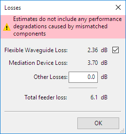
Additional Feeder Losses in Licensed Band

If ODUs are to be mounted indoors or at the base of the tower, or the IRFU or RFU-A has been selected, please see Long Waveguide, instead of using this Losses option.
Secondary Feeder Loss: (PTP 820C 2+2 Only) Shows the amount of feeder loss on the standby path (read only).
Diverse Antenna: (PTP 820C 2+0 SD and PTP 820A 2+2 SD XPIC (BBS) Only) Select the required diverse antenna from the drop down list.
Diverse Antenna Height: (PTP 820C 2+0 SD and PTP 820A 2+2 SD XPIC (BBS) Only) Set the height of the diverse antenna.
Diverse Feeder Loss: (PTP 820C 2+0 SD and PTP 820A 2+2 SD XPIC (BBS) Only) The amount of feeder loss on the diverse end of the link.
Power: (PTP 850 and PTP 820A Only) Choose whether to use PoE or DC power
Ethernet Cable: (PTP 820E and PTP 850 Only) Choose the data drop cable type from Cat 6A and Fiber options.
IDU-RFU Cable: (PTP 820F Only) Choose the drop cable type between the radio and the modem unit from Cat 6A and Fiber options.
IDU-RFU: (PTP 820A Only) Read only. Shows the TCC or RIC-D card RFU interface used and the drop cable type between the radio and the modem unit from Cat 6A and Fiber options.
Tx Frequency: To change transmit frequencies at either end of the link, click on Select.... The Select Transmit Frequencies dialog is displayed. The end of the link which has been selected as Hi will show the higher frequencies in the band, warnings will be displayed for 2+0 if the two Tx Frequencies at the same end of the link are not both in the same part of the band.
If an IRFU has been selected there is also an option to change the Synthesizer Step Size, unless the band is Lower 6 GHz, which operates on a fixed frequency plan. At Upper 6 GHz or 7 GHz the options are 5, 50, 100, 125 and 250 kHz and at 11 GHz the options are 125 and 250 kHz, in both cases the default is 250 kHz. As the filters are tuned to order, a wider range of frequency options are possible with the IRFU, but may not be available from every regulator. Please check local regulatory requirements when selecting frequencies.
Click Clear Selection to remove specific frequencies from the list, the BOM will go back to the default ODU part numbers - before ordering make sure that these are set to the correct part numbers by choosing the appropriate frequencies.
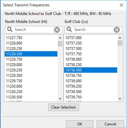
Select Transmit Frequencies
Diversity Separation (PTP 810 Only) When 1+1 Frequency Diversity is selected two Tx Frequency selections will be available at each end of the link. When both frequencies have been selected the Diversity Separation will show the difference between the two frequencies. Separations of greater than 500 MHz will not give any further increase in the improvement factor, see Setting Diversity.
Tx Capacity Limit: (PTP 800 Only) Select the limit that must be applied to data throughput capacity at this end of the link (Mbps). When this is changed, the Throughput data in the Performance Summary section at the OTHER link end may change automatically.
MMU Model: (PTP 810 only.) Select the type of MMU to use for the link.
Max Payload Bytes: (N500 only) Set the maximum packet size. Maximum value is 1600 Bytes. Minimum value for fixed modulation mode is 64 Bytes, in adaptive mode, the minimum may be higher than this dependent on the configured Max and Min Modulation modes. Reducing the packet size will reduce the data rate from the quoted data rate per mode.
Selection of MMU model is dependent on the TDM configuration, additional modules and Ethernet throughput required. Refer to the PTP 810 Series User Guide for further details.