Setting Diversity
Diversity is a method where the same digital information is sent or received over more than one path between the transmitting site and the receiving site, in order to reduce outages and hence achieve better performance of the link. There are several methods to achieve diverse paths and the two that are used in the Cambium PTP products are space diversity (all products except ePMP, N500, PTP 450, PTP 450i, PTP 550 and PTP 820S) and frequency diversity (PTP 810 only).
Space Diversity
In some cases it is necessary to add a second (diverse) antenna to improve the long term performance of the link. Diverse antennas are used to solve two different phenomena, which both cause reflections to be experienced at the antenna. The placement of the second antenna should be such that when one antenna is experiencing a null or faded signal, the other antenna is experiencing a good signal. The choice of antenna separation distance (which is always a vertical separation) is dependent on the mechanism which is causing the reflections.
- Tropospheric Multipath (one example of which is ducting) is where there are many reflections arriving at the antenna and the angles are not constant over time. In this case larger separations are preferred and the availability calculation will show the improvement which can be achieved for a given antenna separation. In general increasing the separation will improve the availability and decreasing the separation will reduce the availability. This will be more obvious in geographic locations which are prone to high levels of tropospheric multipath, in more benign areas the amount of antenna separation has little impact on the amount of diversity gain. The separation distance recommended by the LINKPlanner reflection editor is not for use in combating tropospheric multipath.
- Reflection mitigation Two separate antennas are also used to protect against reflections from objects, most commonly those over water. In this instance the reflections follow the laws of geometry and specific separation distances are required to overcome them. It is therefore important in this case to ensure that the antennas use the separation distances recommended by the LINKPlanner reflection editor, see Unlicensed Band Reflection Editor.
Some links may require spatial diversity to combat tropospheric multipath and provide protection from reflections over water. In this case use the multiplier factor to increase the separation to suit the spatial diversity requirements, but at the same time maintain the required geometrical separation.
Reflections over Water
If the path is over water, it is necessary to detect whether mitigation techniques are necessary, and if they are, to calculate the optimum vertical separation for the diversity antennas. To do this, click Link, Edit Reflection Parameters. Tick the “Enable Reflection Mitigation” box (Unlicensed Band Reflection Editor or Licensed Band Reflection Editor) to enable the calculation and display a visualization of the reflection on the Profile chart. The Reflection Surface Height (blue line with gray ends) will normally be aligned with the height of the reflecting surface, if it isn’t adjust the Reflection Surface Height until the line aligns with the height of the reflecting surface.
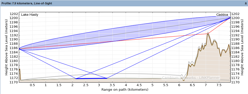
Profile with Reflection Visible
If the reflected paths have an unobstructed route to both ends of the link, as shown in Profile with Reflection Visible then mitigation techniques are required. The simplest technique is to obstruct the reflected path, on this link the path can be obstructed by lowering the Caddoa antenna (Profile with Reflection Obscured). This makes diversity spacing unnecessary for reflection mitigation, because the reflection path is obscured by the hill in front of the Caddoa antenna.
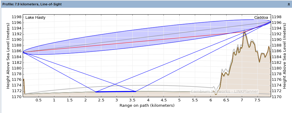
Profile with Reflection Obscured
If the reflected path cannot be easily obstructed then spatial diversity will be required.

LINKPlanner does not adjust the reliability of the link based upon the possible reflection, but a link that suffers reflection can have very bad performance if the mitigation has not been applied.
Unlicensed Band Reflection Editor
Unlicensed products use both Tx and Rx diversity and therefore diversity should only be applied at one end of the link. The diversity separation ensures that both antennas are not fading simulataneously, however this means that it is only the single payload modes which have full protection against reflections.

LINKPlanner will only guarantee the performance of single payload modes in the presence of reflections. When the reflection mitigation option is ticked the Performance Summary and Performance Details will only consider the single payload modulation modes.
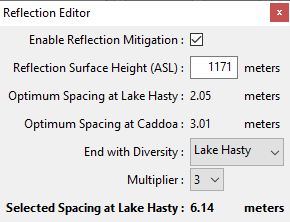
The reflection editor shows the Optimum Spacing at each end, see Unlicensed Band Reflection Editor. The optimum spacing may be different for each end of the link. Choose the end of the link to apply the diversity spacing based on the physical constraints of the towers.
The optimum spacing is the smallest spacing that will cancel the reflection, however it may not be possible to install the antennas at this separation, depending on the size of antennas selected and mounting points available. If a larger separation is required choose a Multiplier from the pull down list to give a suitable spacing shown as the Selected Spacing. In the example above, the Multiplier is set to 3 to give a spacing of 6.14 meters, which is easily achievable without much cable loss.
The unlicensed band radios are mounted to external antennas to provide diversity spacing. The Optimum Spacing requires the minimum cable length and hence the minimum additional loss from the single radio unit to both antennas. When using a larger multiplier the antennas are further apart and require longer cables to connect from the radio to the two antennas, increasing the additional loss.
For unlicensed products set the Multiplier, then transfer the resulting Spacing value to the Configuration Diversity Spacing and tick the Reflection Mitigation box, as described in Configuration at Each End. If diversity is to be applied at both ends of the link, the Diversity Spacing at each end of the link should be entered as half the value given for each end by the Reflection Editor.
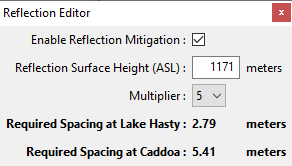
Licensed band products only use Rx diversity and therefore diversity must be applied at both ends of the link using the full diversity spacing values given, see Licensed Band Reflection Editor. Licensed band products have a radio for each antenna which can be directly mounted to the antenna, hence there is no difference in performance if a larger separation is required. If a Multiplier is to be used, select the value from the pull down list to give a suitable Required Spacing at each end of the link. Subtract the diversity spacing from the Primary antenna height to give the height required for the Secondary antenna.
Licensed Band Reflection Editor
For more information about reflections, see Paths Over Sea or Very Flat Ground.
Multipath Reflections
The problem is not easily solved deterministically for reflections due to multipath, because there are a very large number of reflections. LINKPlanner shows the improvement in availability when you select a second antenna and define a separation between the two. If you increase the spacing, the availability increases. If you decrease the spacing, the availability decreases. Adjust the combination of antenna size, antenna height, and antenna spacing to meet the availability requirements.
The unlicensed products incorporate two transmitters and receivers, however both of these are used under normal conditions to provide dual payload throughput. When a diverse antenna is added the two polarizations are split between the two antennas, but there are no additional receive chains to apply protection to the individual polarizations. A licensed band link that supports spatial diversity, as a minimum, includes an extra receive chain to receive the same data from both antennas. In the unlicensed band the dual polarizations are used to provide additional robustness to the single payload modes, which can be at the expense of the dual payload modes.
Splitting the paths between two antennas improves the probability that both will not fade simultaneously, but it also doubles the probability that one of them will have a fade, which reduces the availability of the dual payload modes. It is therefore common to see a link which shows better availability in the dual payload modes without diversity compared with when diversity is enabled. Links which are mostly using dual payload are likely to see a reduction in throughput when diversity is added, however the probability of the link dropping out completely is reduced with diversity.
Configuring Spatial Diversity in LINKPlanner
The PTP equipment operates differently in the licensed (6 GHz and above; PTP 800, PTP 810, PTP 820C and PTP 820G) and unlicensed bands (below 6 GHz; PTP 250, PTP 300, PTP 400, PTP 500, PTP 600, PTP 650, PTP 670 and PTP 700). This affects the way in which the equipment may be deployed for space diversity.
Unlicensed
The unlicensed equipment uses two transmit chains for all configurations and hence when two spatially separated antennas are used one antenna is transmitting and receiving on the vertical polarization and the other antenna is transmitting and receiving on the horizontal polarization. This means that spatial diversity improvement gain is achieved in both directions of a link by deploying separate antennas at just one end of the link. In the unlicensed band the spatial diversity is designed to protect the performance in the single payload modes, but will also offer improvement in dual payload modes when the receive levels on both paths are less than 7 dB apart, however in deeper fades the products will revert to single payload.
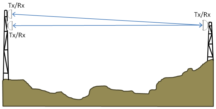
Space Diversity Deployment (unlicensed bands)
In the unlicensed band spatial diversity is automatically applied when a single polarity antenna is selected. The default spacing is set to 5m (16.4 ft), this can be adjusted to suit the local conditions and the availability requirements. If the diversity spacing is set to 0, no additional benefit will be added to the availability. When a single polarity antenna type is selected, a quantity of two per end is included in the BOM. The two antennas at the same end of the link need to be installed on opposite polarities to match the dual polarity unit at the opposite end of the link. If the spatial diversity is required to overcome reflections then tick the Reflection Mitigation box.
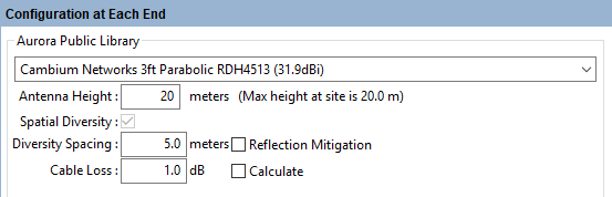
Configuration of Space Diversity (unlicensed bands)
Licensed
The licensed band equipment only has a single transmit chain and therefore only the main antenna is transmit and receive, the diverse antenna is receive only. To achieve spatial diversity gain improvement in both directions of the link, antenna separation is required at both ends of the link. If diversity is only deployed at one end of the link, the availability of the link will be dictated by the non-diverse direction.
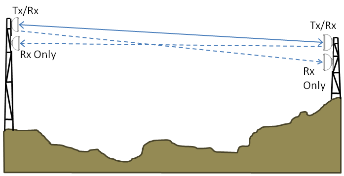
Space Diversity Deployment (licensed bands)
In the licensed band (except for PTP 820C) spatial diversity is achieved in combination with 1+1 Hot Standby Protection. To configure a link to use space diversity, set the Link Type to 1+1 Hot Standby and at both ends of the link set the Antenna Configuration to Spatial Diversity. Set the Primary and Secondary antenna heights at each end of the link to the heights required and the Diversity Spacing value will automatically update to show the difference in antenna height of the primary and secondary antennas. Adjust the heights of the two antennas to give the required availability. Check the Excess Path Loss of the Primary to Primary, Primary to Secondary and Secondary to Primary paths to ensure that all paths are LOS.
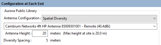
Configuration of Space Diversity (licensed bands)
If the spatial diversity link is configured with ODUs or RFU-A (Split End) (as opposed to IRFU or RFU-A (Standard)) then both antennas have the potential to be Tx /Rx antennas if the end fails over from primary to secondary. The choice of secondary antenna in this case needs to take into account that it may not be receive only or the link must be configured not to switch over the transmit on failure, for further information see the User Guide for the product.
If the link is configured with IRFUs or as RFU-A (Standard) the transmit chain from both modems is connected to the primary antenna and the secondary antenna is receive only.
For further information on setting spatial diversity for PTP 800, PTP 810, and PTP 820G products, see Setting Hot Standby Protection (1+1).
To configure a link to use 2+x space diversity, set the Link Type to 2+0 Spatial Diversity (PTP 820C), 2+2 Spatial Diversity (PTP 820C) or 2+2 SD XPIC (BBS) (PTP 820A) and then set the antenna type and height for both Main and Diverse at each end of the link in the Configuration at Each End section. In the 2+0 configuration only the Main antenna will transmit and therefore the only valid paths between the two ends are Main to Main, Main to Diverse and Diverse to Main, to view these paths on the Path Profile set Path to display to the required option, see Profile. In the 2+2 configuration the Diverse antenna can also transmit and therefore must also be a compliant antenna and the Diverse to Diverse path is available in the Path to display options.
For PTP 820C there are several cables required between the two radios at each end of the link, which have a maximum cable length of 20m. This restricts the maximum allowed diversity spacing to 18m.
Height Clearance
When planning a diversity link it is important to ensure that all paths have sufficient clearance. For licensed band links all paths must be Line of Sight and it is advisable even for unlicensed links. Any additional path loss on the diverse path will not be taken into account in the availability calculations, therefore if some paths are not LoS the predicted availability will be optimistic.
In addition to ensuring LoS, the path between the two main antennas should give clearance over the Worst Earth curvature (grey line), however other paths may allow some penetration of this area into the Fresnel zone.
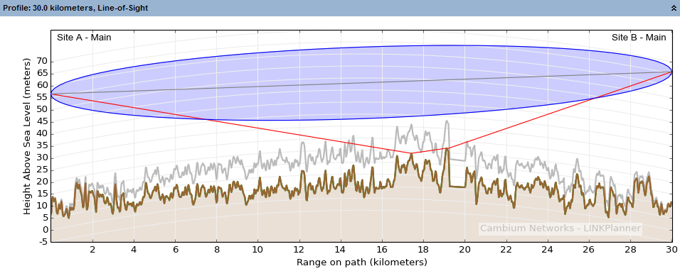
Height Clearance between main antennas
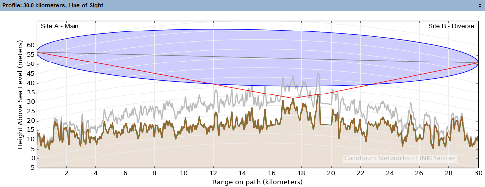
Height Clearance between main and diverse antennas
Frequency Diversity
Frequency diversity uses a single antenna at each end of the link, but uses two transmitters at each end to send the same digital information over the same physical path on two different frequencies. The amount of diversity gain achieved for a given link is dependent on the path length, center frequency, frequency separation and fade margin.
Frequency diversity can be used to overcome the same phenomena as space diversity, although it is more commonly used only to combat atmospheric multipath where space constraints prevent the use of spatial diversity. As two frequencies are required it is less spectrally efficient than spatial diversity and is not permitted by all regulators, check with the local regulatory agency.
Frequency diversity is only available when a PTP 810 product is selected at frequencies of 6 GHz and above. It is then available from the Link Type menu (1+1 Frequency Diversity), except in the FCC regulatory region where it is not permitted to be used.
Improvement Factor Equations
The diversity gain improvement equations are taken from ITU-R P530, using the method given in section 6.2.5 to calculate outage for space and frequency diversity. These algorithms are primarily aimed at long paths above 25 km (15 miles) and for frequencies up to 11 GHz. Care should be taken if applying diversity to shorter paths or those at higher frequencies. At higher frequencies rain becomes the dominant factor in the availability calculation and diversity does not provide any improvement against rain fading, therefore adding diversity will give very limited improvement at higher frequencies.
When using the space diversity algorithm the separation distance is valid between 3 and 23m (10 and 75ft). For frequency diversity, the frequency separation should not be more than 5% of the central frequency and is limited at 0.5 GHz, these constraints are met within the range of frequencies available in each band.