TDD Synchronization Overview
The performance of any radio is dependent on the level of electromagnetic interference to which it is subjected. This is also the case for the PTP Outdoor Units (ODUs).
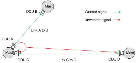
PTP ODUs are installed as pairs to form a Point to Point radio link. In an ideal radio environment, any individual ODU will receive transmissions only from the paired ODU at the other end of the link. However, when multiple links are installed, an ODU may also be subjected to interference from the transmission of an ODU which is part of another link. This is depicted in Interference Between ODUs, which shows an example concentrating specifically on ODU A as an interferer. Both ODU C and ODU D are subjected to interference from ODU A.

Interference Between ODUs
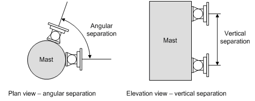
Interference between units on the same mast is the most problematic due to their close proximity. The problem becomes worse when the angular separation between links (see Separation of PTP 670 Units on a Mast) is small. This can be alleviated by using the following techniques:
- Increasing the separation between the victim’s receive frequency and the interferer’s transmit frequency. With limited spectrum, this becomes more difficult with increasing numbers of links.
- Increasing the physical separation between the interferer and the victim. Separation of PTP 670 Units on a Mast vertically separated on a mast.
- Reducing the transmit power of the interfering radio. However, this may affect the performance of the interferers own link in the direction away from the common mast.

Separation of PTP 670 Units on a Mast
The techniques for minimizing interference on a common mast are described in PTP 600 Series Deploying Collocated Units, where the same techniques are applicable to PTP 670 and PTP 700. If these techniques do not reduce interference sufficiently, then TDD synchronization should be considered.
TDD synchronization works by aligning the frames of all links in the network thereby eliminating interference between those ODUs which are configured to operate on the same phase of the TDD cycle. To understand this, it is first useful to consider the TDD frames of the two links shown in Separation of PTP 670 Units on a Mast with synchronization disabled.
Unsynchronized Links
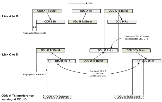
When the frames of two links are unsynchronized, the transmission from one ODU may overlap the receive frame of any another ODU. Unsynchronized Frames shows the frames of the two links “A to B” and “C to D”. The diagram focuses on ODU A as the interferer. It can be seen that the transmission from ODU A is overlapping the receive period of both ODU C and ODU D. As well as the frames not being aligned, the frame duration of link “C to D” is longer than that of link “A to B”. This is because the propagation delay of this link is longer. This means that the size of the overlap will vary from frame to frame. This is illustrated by the overlap period with ODU D Rx being longer in the first frame than in the second frame.

Unsynchronized Frames
Synchronized Links
The primary advantage of TDD synchronization is that the network can be configured such that the transmit burst of an ODU does not overlap the receive burst of a collocated ODU. This eliminates the most problematic interference mechanism.
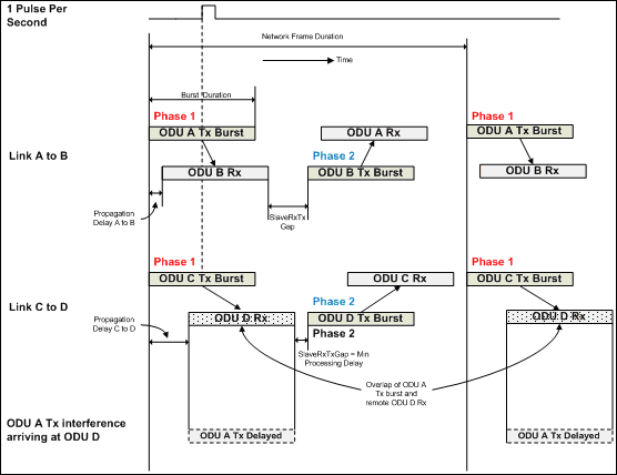
Taking the same example pair of links, Synchronized Frames shows the two links with TDD synchronization enabled. The start of each frame now occurs at the same point in time. This is achieved by the use of a GPS synchronization box which injects a pulse into the Master ODU every second. One GPS synchronization box is required for each Master ODU and the pulse occurs at the same point in time for every GPS synchronization unit in the network. The Master ODU then offsets the center of its frame relative to the pulse by a configurable delay. The intention of this delay is to allow the Master to be configured to transmit on either Phase 1 (which is when the pulse aligns with the center of the Master transmit burst) or Phase 2 (which is when the center of the Master transmit burst is delayed by half the frame duration relative to the pulse). The default is for Masters to be on Phase 1 which is suited to the common case of collocating Master ODUs at “hub” sites.
In Synchronized Frames, collocated ODUs A and C transmit on Phase 1, i.e. the 1 pulse per second aligns with the center of the transmit burst. The remote ODUs B and D transmit on Phase 2, 180 degrees out of phase with ODU A and C.
The result of TDD synchronization is that the receive period of ODU C never overlaps with the transmission burst from the collocated ODU A - and vice versa. Also, the receive period of remote ODU B never overlaps with the transmission burst from remote ODU D - and vice versa. However, the receive period of the remote ODU D still overlaps with the transmission from ODU A. In fact, they are now perfectly aligned. This highlights the key result of TDD synchronization which is that half of the network interference mechanisms are eliminated, or more precisely, the interference between units operating on the same phase of the TDD cycle is eliminated.
In order to eliminate interference between units which are on the same phase but which are NOT collocated, the propagation delay of the victim link and the interference path needs to be considered. This leads to the optimization of three parameters:
- Burst Duration
- Frame Duration
- slaveTxRxGap
Burst Duration and Frame Duration are self explanatory and are shown in Synchronized Frames. The parameter slaveRxTxGap is also shown in Synchronized Frames and allows the frames of shorter links to stretch to that of the longest link in order to keep a common network frame duration. This highlights a key disadvantage of TDD synchronization in that the efficiency of shorter links reduce to those of the longer links. Also note that adaptive frame structures are no longer possible. In fact, only symmetrical frame structures are supported when TDD synchronization is enabled.
Optimization of these parameters as well as the configuration of phase using Link Planner is discussed in Setting TDD Synchronization.

Synchronized Frames