Setting 2+0 Antenna Sharing
2+0 antenna sharing is available on PTP 550, PTP 700, PTP 800, PTP 810, PTP 820 and PTP 850 links. How to configure 2+0 depends on the product and whether an outdoor or indoor RFU is used:
- PTP 550 and PTP 550E require a single RFU with either an integrated or dual polar antenna
- PTP 700 requires two RFUs at each end of the link to operate through a common coupler to a single antenna
- PTP 800, PTP 810, PTP 820S and PTP 820G require two RFUs at each end of the link to operate either through a common coupler to a single antenna or a dual polar antenna to provide two parallel links between two sites.
- 2+0 Co-Polar with an IRFU combines the two paths through an additional circulator to a single antenna, removing the loss of the coupler.
- PTP 820C, PTP 820F with RFU-D, PTP 820A with RFU-D and PTP 850C require a single RFU and either an OMT or splitter with a single polarity antenna.
For a more detailed understanding of 2+0 Antenna Sharing, see the appropriate product User Guide.

2+0 antenna sharing using outdoor RFUs is not available for some bands, regulations, T/R spacings or bandwidths, for PTP 800 and PTP 810, see the product User Guide for further information. For PTP 820 ensure that the two pairs of frequencies are in the same sub-band.
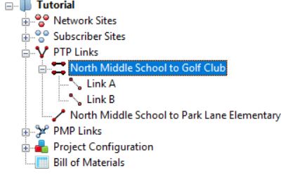
2+0 antenna sharing can be enabled as described in Link Description and Equipment, for 2+0 Co-Polar (ACCP), 2+0 Cross-Polar (ACAP) and 2+0 XPIC (CCDP) (PTP 810 or PTP 820 Only). For PTP 550 and PTP 700 there is only one 2+0 option available. For PTP 800i with IRFU the only option is 2+0 Co-Polar, all 3 options are available for PTP 810i with IRFU, with the 2+0 Cross-Polar and 2+0 XPIC using dual polar antennas. Once enabled, the Project Navigation Tree expands to show a link node and its two associated links Link A and Link B. The 2+0 Cross-Polar is shown in Navigation Tree for 2+0 Cross-Polar link.
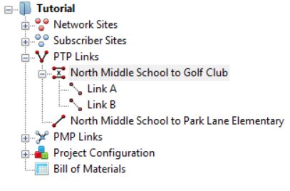
It is differentiated from the 2+0 Co-Polar, which is shown in Navigation Tree for 2+0 Co-Polar link, by the ‘x’ between the parallel lines in the link icon.
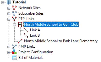
The 2+0 XPIC configuration, which is shown in Navigation Tree for 2+0 XPIC link, is differentiated by the ‘XPIC’ between the parallel lines in the link icon.
For PTP 700 and PTP 800 the link node gives access only to the Link Description, Region and Equipment Selection and Bill of Materials aspects of the link configuration, see Link Node Information for PTP 800 2+0. PTP 550, PTP 810 and PTP 820 also display all Equipment parameters, the Performance Summary and Performance Details for the aggregated link, see Link Node Information for PTP 810 2+0. For PTP 810 and PTP 820G the number of STM-1 (PTP 810 Only) and E1 or T1 circuits is configured for Link A and Link B at the link node level and cannot be changed at the lower levels. Click either Link A or Link B to configure the individual path settings.
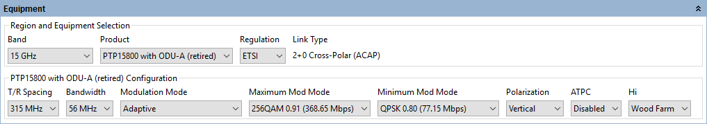
2+0 Equipment Configuration
The Region and Equipment Selection information is repeated from the link node configuration for all products. The Link Type and TDM Configuration (PTP 810 and PTP 820G only) cannot be changed at this level, however the other parameters can be changed and any changes will be reflected in the other link. For PTP 800 click either Link A or Link B to set up the product section of the equipment configuration, for PTP 810 and PTP 820 this is also repeated from the link node configuration. For PTP 800 the product configuration settings can all be changed independently for Link A and Link B with the exception of the Polarization, which is shared for the 2+0 Co-Polar option and is reversed from Link A to Link B when 2+0 Cross-Polar is selected. For PTP 810 and PTP 820 the product configuration information is all shared, with the following exception:
- Polarization, which operates the same as for PTP 800, also being reversed from Link A to Link B when 2+0 XPIC is selected.
For PTP 810 only supports bandwidths of 28 MHz or greater. For PTP 810 2+0 XPIC also only supports Fixed Modulation Modes of 64 QAM or higher. XPIC is only valid on LOS links, if the link has any Excess Path Loss the Throughput and Availability predictions will be set to zero. The link must be LOS in order to achieve the required polarization discrimination for XPIC operation.
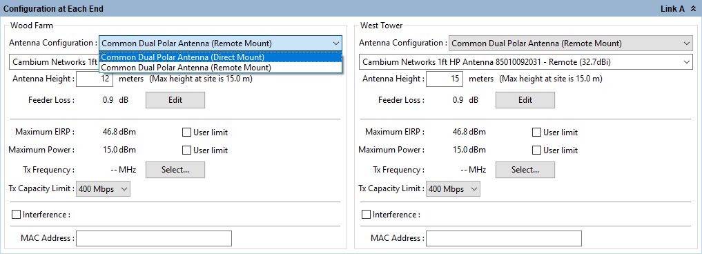
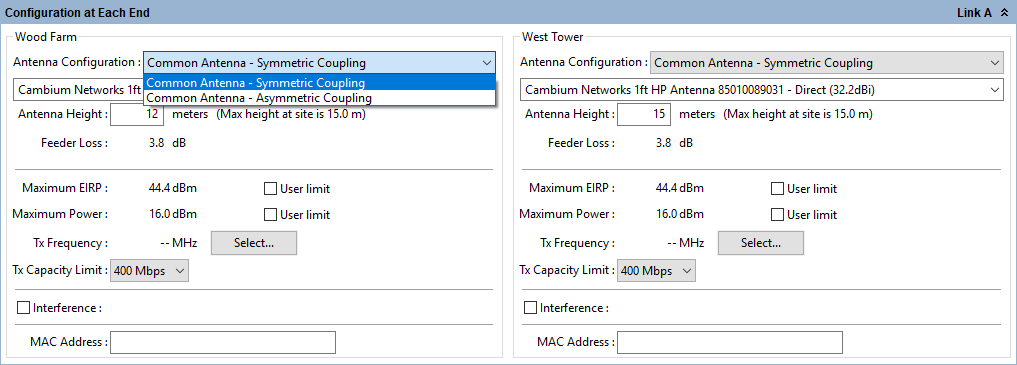
2+0 Configuration at Each End
The Configuration at Each End panel includes the following additional attribute for the PTP 800 and PTP 810 ODU products:
Antenna Configuration: There are 2 options which can be selected to match the possible configurations for 2+0 Cross-Polar and 2+0 XPIC
The parameters at each end for each link can be configured as described in Configuration at Each End. Although the parameters can be configured through either Link A or Link B, some parameters are common to both links. Any changes made to either link configuration will automatically be reflected in the other configuration.
Antenna Type: The antenna type will always be the same for both links.
Antenna Height: The antenna height will always be the same for both links.
Feeder Loss: This field will always be the same for both links. In the case of 2+0 Co-Polar this field will incorporate the coupler loss in addition to any waveguide loss, for an ODU. The symmetric coupler will have the same loss for both links (maximum 4.5 dB), whereas the asymmetric coupler has a lower loss for Link A (maximum 2 dB) and higher loss for Link B (maximum 7.4 dB). For an IRFU, Link B will only incorporate additional circulator losses of up to 0.7 dB compared to Link A, when using 2+0 Co-Polar and will have the same loss for both Link A and Link B when using 2+0 Cross-Polar or 2+0 XPIC.
Maximum EIRP: This field can be set independently for the two links.
Maximum Power: This field can be set independently for the two links.
Tx Frequency: This field must be different for Link A and Link B for 2+0 Co-Polar and 2+0 Cross-Polar. When using 2+0 Cross-Polar adjacent channels may be used and also for PTP 820 2+0 Co-Polar. When using PTP 800 and PTP 810 2+0 Co-Polar adjacent channels may be selected but are not preferred and a warning will appear, see Select Transmit Frequency 2+0 Co-Polar Adjacent Channel Error. 2+0 XPIC uses the same Tx Frequency for both links and hence the value will always be the same for both links.
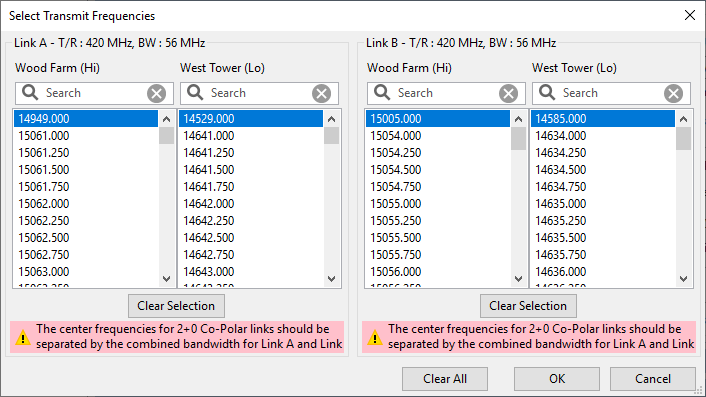
Select Transmit Frequency 2+0 Co-Polar Adjacent Channel Error
Tx Capacity Limit: PTP 800 Only. This field can be set independently for the two links.
MMU Model: PTP 810 Only. The MMU model will always be the same for both links at the same site, but can be different at each end of the link.
Interference: This field can be set independently for the two links.
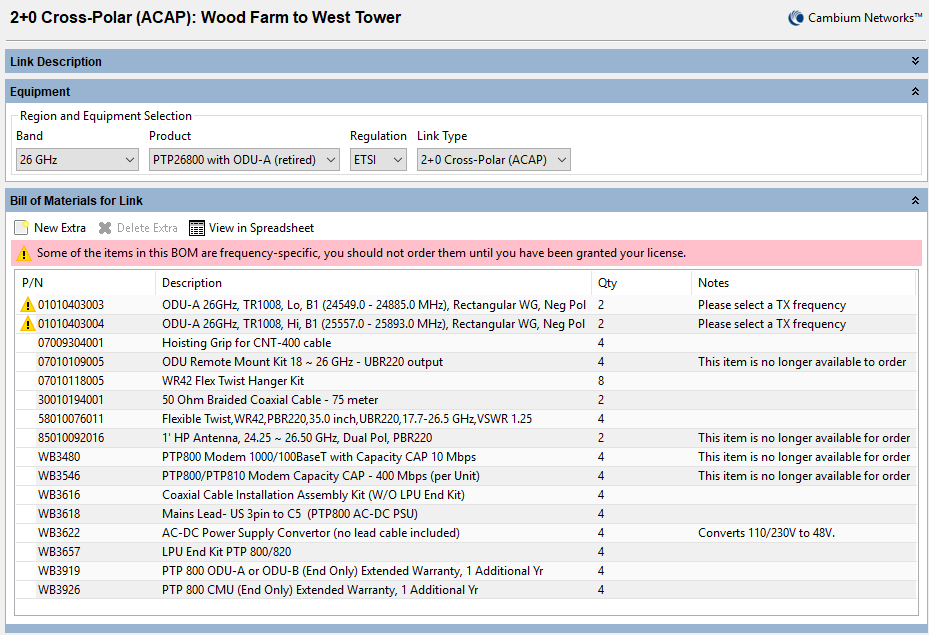
2+0 Bill of Materials
The Bill of Materials is displayed at the link node level and shows the full set of equipment required for both Link A and Link B.
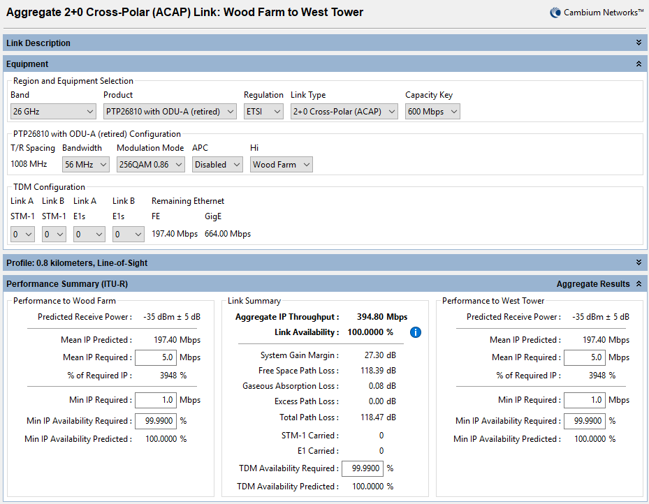
2+0 Performance Summary
The performance summary information for each link is shown on the link page for Link A and Link B. For all products the required performance parameters can be set independently for each link and are defined in the usual way, see Performance Summary. For PTP 810 and PTP 820 the aggregate performance summary is also available at the link node level, where the parameters are defined in the usual way. If the predicted performance of either link is below requirements, then the main link will be displayed in red. PTP 810 and PTP 820 links will display the main link in red if the aggregated performance is below requirements, even if Link A and Link B satisfy their requirements.
2+0 Reports
The reports for 2+0 configurations are created at the link node level in the usual way, see Creating Reports. PTP 800 reports contain the performance and installation information for both links. In the installation report, where the equipment is common to both Link A and Link B, the information in the installation notes is only given for Link A. PTP 810 and PTP 820 reports contain the performance of the aggregate link and the installation information required for both links.