cnRanger Network Design Process
This section provides a process to design a cnRanger network for experienced Windows or Mac users. It describes how to build a cnRanger network with multiple hubs, Baseband Units (BBUs), Remote Radio Heads (RRHs) and Subscriber sites in a few simple steps.
Before starting this process, complete the following steps:
- Install the software in the usual way. See Installing LINKPlanner.
- Start the application.
- Enter the correct details in the Options (Preferences) page. Ensure that Email address and Network Settings are correct. See Options (Preferences).
- Register with the path profile service. See Options (Preferences).
Build the network in five simple steps:
Add network sites from csv or kml. See Copying or Importing Sites.
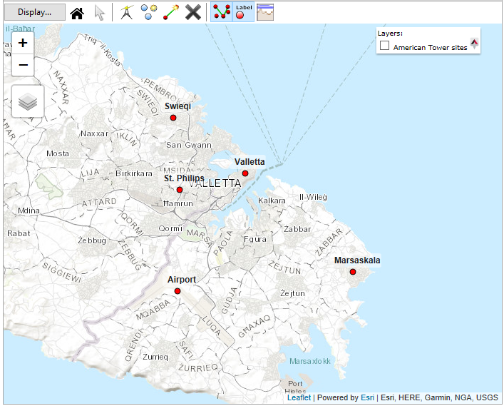
cnRanger Network Sites Added
Add subscriber sites from csv or kml. See Copying or Importing Sites.
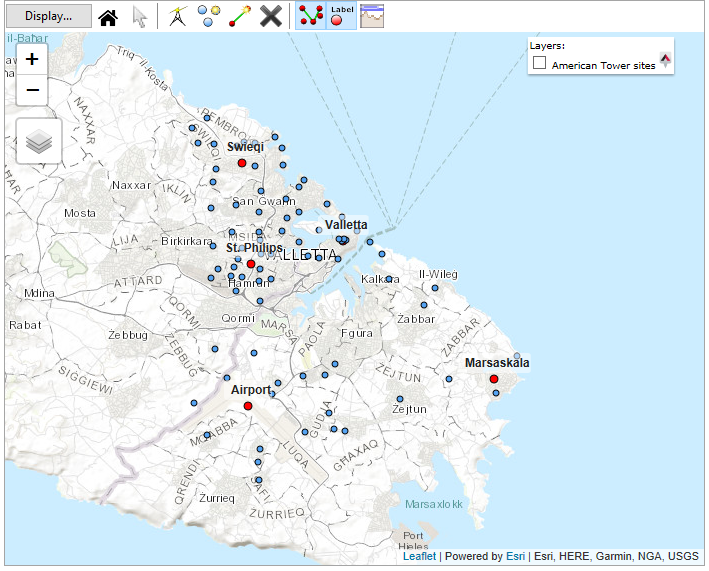
cnRanger Network with Subscriber Sites Added
Create a cnRanger PMP Equipment Template. See Equipment Templates.
To create a template, click on PMP Equipment Templates in the Project Configuration section of the Navigation Tree.
cnRanger uses the same LINKPlanner structure as other PMP products with the Global Radio and Site settings and the RRH specific functionality mapping onto an Access Point.
Configure the Access Point Equipment section of the template with the BBU and RRH parameters.
Start by setting the band according to the required LTE Band, for LTE Band 38 choose 2.6 GHz, for LTE Band 40 choose 2.3 GHz and for LTE Band 41 choose 2.5 GHz. For this example set the Band to 2.5 GHz and the Product to Palisade 220 for the RRH equipment.
Configure the RRH parameters:
Bandwidth: 20 MHz
Range Units: kilometers
SM Range: 3.0 km
Max Registrations Allowed: 64
Downlink Data: 67% (TDD config 3)
SSF: 6
Antenna Selection: Cambium Networks 90/120 Degree Sector Antenna
Modeled Beamwidth: 120 degrees
EIRP: 50 dBm (read only)
Power: 36 dBm (read only)
User Limit: Unticked (tick this box to reduce the transmit power)
AP Interference: Unticked (tick this box to add external interference at the RRH)
Default SM Interference: Unticked (tick this box to add the same external interference to all subscribers on the RRH)
The combination of Downlink Data and SSF (Special Subframe) controls the network synchronization and the SSF options available are dependent on the SM Range.
The transmit power is entered in LINKPlanner as the combined power for both Tx branches, which is 3 dB higher than the Tx power per branch.
There are no configurable items at the template level for the Subscriber Equipment.
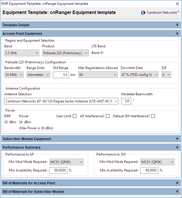
cnRanger PMP Equipment Template
Add hub sites and access points. See Hubs.
To create a new Hub, either click Project, New Hub or click New Hub
 . The New Hub page is displayed.
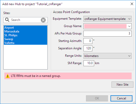
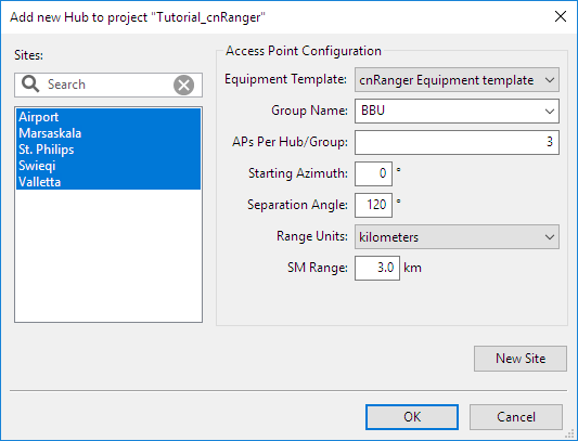
cnRanger Add New Hub configuration window
For cnRanger networks the group represents a BBU, which can support a maximum of 3 RRHs, shown above as APs Per Hub/Group. Type a name into the empty space for the Group to add a new group name.
Configure the options:
Group: BBU
APs Per Hub/Group: 3
Starting Azimuth: 0 degrees
Separation Angle: 120 degrees (will update automatically when the number of APs is changed if not previously edited)
Range Units: kilometres
SM Range: 3.0 km
Select OK to add the sectors to the hub sites. As the RRHs are created each one is allocated an RRH number from 1 to 3 in the order they are created in each group. To change the RRH number select the AP/RRH in the navigation tree and choose a new value in the drop-down list. Each group must contain unique RRH numbers to match the way the equipment is defined on the BBU.
cnRanger Add New Hub Completed
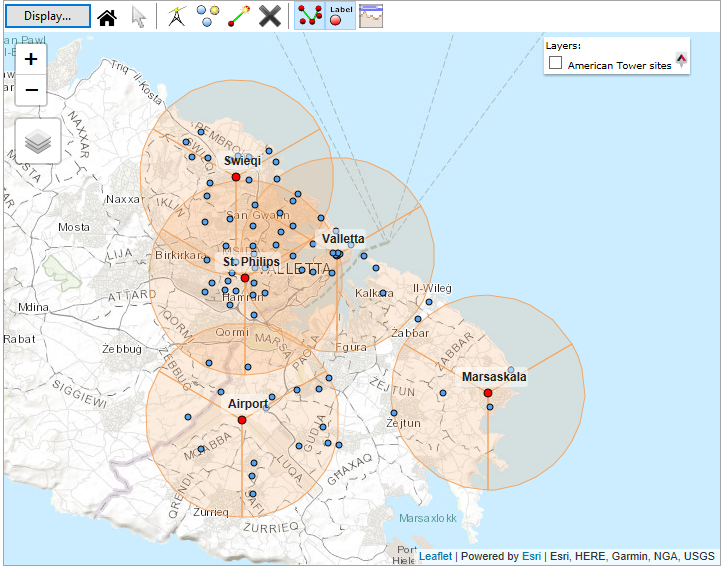
cnRanger Network with Hubs and Access Points
To add another BBU to a hub site repeat the process in this step using a different group name.

- All RRH in the same BBU group on a hub must have the same Band, Bandwidth, Downlink Data and SSF. Warnings are shown if they are not set to the same values.
- A group on a hub that contains an AP configured as an RRH with cnRanger equipment cannot also contain APs using other products.
- When a group contains cnRanger RRHs then the BBU equipment is added automatically to the group and the New Extras contain additional cnRanger specific equipment.
- The network equipment Proposal and Installation reports for cnRanger are generated at the BBU level and the same report is produced if selected at the BBU group or from any of the RRHs on the BBU Group. To generate a group level report select the Hub in the Navigation Tree, then select the BBU group tab and either Proposal Report
 or Installation Report
  . To create a BBU group level report as a PDF select an RRH from the group in the navigation tree and click File, PMP Proposal Report or File, PMP Installation Report and then select Access Point.
Connect subscribers using Best Server Analysis. See Best Server Analysis.
Set the Group to the required BBU layer and tick Tyndall 101 to select the SM.
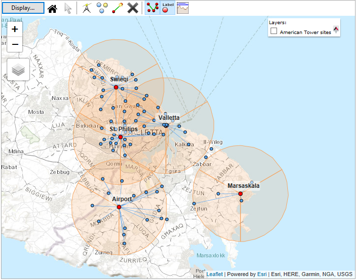
cnRanger Network Connected
For more information on designing an individual PMP link, including adding individual sites, connecting a single SM to an RRH and understanding the performance of individual PMP links, see PMP/HCMP Tutorial