LINKPlanner Concepts
NLoS and LoS
The Cambium Networks Series of point-to-point (PTP) wireless Ethernet bridges and point-to-multipoint (PMP) wireless broadband solutions are designed to operate in non-line-of-sight (NLoS) and line-of-sight (LoS) environments. Link planning and estimation enable a link of known quality to be installed. LINKPlanner uses path profile data to predict the data rates and reliability over each link, through adjustment of antenna height and RF power. When the link is installed, the mean path loss can be checked to confirm these predictions.
Architecture
The LINKPlanner is an application that runs on Windows or Macintosh. It performs the calculations from the ITU recommendations ITU-R P.526-10 (without clutter) or ITU-R P.526-14 (with clutter) and ITU-R P.530-12, ITU-R P.530-17 or Vigants - Barnett (VB) to predict NLoS and LoS paths for anywhere in the world. Path profile data can be obtained in a number of different ways depending upon global location. Cambium provides a method for obtaining path profile data; see Path Profiles. Trees and buildings (clutter and obstructions) can modify this profile, and often the path must be surveyed to establish the correct estimation.
The main concepts of LINKPlanner are:
- Project: a set of data about the sites and links in a wireless network.
- Network Site: the location of a PTP outdoor unit and its antenna or a PMP Hub Site.
- Subscriber Site: the location of a PMP Subscriber Module outdoor unit and antenna.
- Hub Site: a location which contains one or more Access Point or RRH outdoor units and antennas. Groups on a hub site allow the equipment on the hub site to be divided into layers. For cnRanger a group represents a BBU and its associated equipment.
- Access Point: (RRH for cnRanger, BTS for cnWave 5G Fixed or DN for 60 GHz cnWave) an outdoor unit and antenna which connects to multiple Subscriber Modules.
- Subscriber Module: (CPE for cnWave 5G Fixed or CN for 60 GHz cnWave) an outdoor unit and antenna at a customer or remote premises.
- Link: a wireless connection between two PTP sites or between an Access Point and a single Subscriber Module.
- Path: an alternative wireless link between two PTP units at different sites, when each site has multiple units.
Inputs and Outputs
The main inputs to LINKPlanner are:
- Site name, position, maximum antenna height and site definition; network or subscriber (input by the user).
- Details of the equipment and license restrictions (selected by the user).
- Required performance targets for each link or network (input by the user).
- Profile of the terrain and (optionally) clutter along the path of each link (obtained using a Cambium tool).
- Details of any obstructions or reflections that may affect the performance of a link (obtained from maps, survey data and Google Earth(TM)).
The main output from LINKPlanner is a performance summary that shows how well the link is predicted to perform in response to the selected combination of inputs. It shows predicted and required throughput performance and availability at each end of the link.
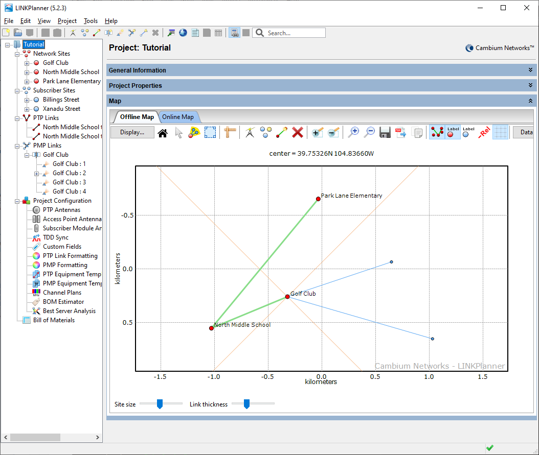
User Interface
The following example shows the LINKPlanner User Interface for the “Tutorial” project, which models a PTP network linking three sites, one of which is also a Hub Site containing one Access Point, which is connected to two Subscriber Modules: